User instructions
All required functions are initially accessed from the 'Nesting' folder icon on the start-up screen, double clicking this will produce a window containing icons for the following main functions:-
Icons:-
Console
Pre-processor
Geoviewer
Post processor
Interactive, (manual), nesting
Nest viewer
Clean-nesting
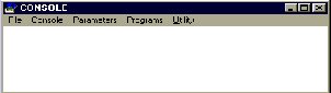
These can all be accessed via their individual icons or, more easily, through the toolbar on the 'Console window'-once this has been opened.
The basic stages in generating part programs for the GFM US40 cutting machine are:-
Stage Involves 1 Building the Nest table Setting the Pre-processor parameters for CAD file conversion of patterns required Setting allowable ply rotations Defining part & ply identities required for ink jet printing Pre-processor conversion of IGES into GEO files then, either 2 Automatic Nesting Defining order of pattern selection for Auto nesting Auto Nesting and generation of Nest result files (.000) Printing out of Nest result files as Grafic reports Identification of machine Part programs produced,(.obj files) or, 3 Interactive nesting Uses of Interactive nesting Interactive Nesting and generation of Nest result files Generation of machining, (.obj) files Modification of existing Nest result files Re-Posting of edited Nest tables and Nest result files